IN TODAY'S POST LETS SEE WHAT IS SPI. For programming part see SPI tutorial in Arduino
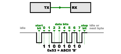 (By the way, plz noticed that "11001010" does not equal 0x53 in the above diagram.Serial protocols will often send the least significant bits first, so the smallest bit is on the far left.The lower nubble is actually 0011=0x3, and upper nybble is 0101=0x5.)
 One reason that SPI is so popular is that the receiving hardware an be a simple shift register. This is a much simpler piece of hardware that the full-up UART (Universal Asynchronous Receiver/ Transmitter) that asynchronous serial requires.
introduction:
Serial peripheral interface [SPI] is an interface bus commonly used to send data b/w microcontroller and small peripherals such as shift registers, sensors, SD cards and other controllers.It uses separate clock and data lines and differentials devices using select lines.
What's the difference b/w Serial Ports?
Serial ports normally use TX and RX lines which are "asynchronous"and there is no control over when data is sent or Guarantee that they are receiving the data at the same time or following at a same rate. So they should have same clock else they will not communicate properly. So to handle this problem asynchronous serial connections add extra start and stop bits to each byte to help receiver to sync with each other.SPI: AS SOLUTION
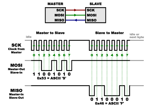
SPI works in a slightly different manner. it's a "synchronous" data bus, which means that it uses separate lines for data and a "clock" that keeps both sides in perfect sync. The clock acts like a indicator to the receiver. HOW WILL THE RECEIVER KNOW WHEN THE DATA IS COMING? ITS SIMPLE IT KNOW THAT BOTH THE CLOCK AND DATA COME AT THE SAME TIME.
Receiving Data:
Sending data may seem really simple where as Receiving data is slightly complicated.In SPI, only one side generates the clock signal (usually called CLK or SCK for Serial Clock). The side which generates the clock is called the "master", and the other side is called the "slave" which can be many.
When data is sent from the master to a slave, it's sent on a data line called MOSI, for "Master Out/ Slave In". If the slave needs to send a response back to the master, the master will continue to generate a prearranged number of clock cycles, and the slave will put the data onto a third data line called MISO, for "Master In / Slave Out".
Notice we said "prearranged" in the above description.We know when the master gets the data from the slave so we need to give clock cycles at that moment to receive them.For example we know by sending command "read data " we know some data is coming so we will allot some clock cycles.
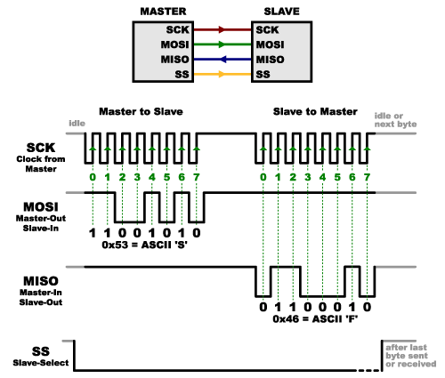
Slave Select(SS):
Now the last pin we need to know is the Slave Select which tells the device when to wake up and receive or send data.
This line is active low that means we need to give a "logic 0" to enable it.Now how to use it ?
When sending a data we make the pin low and send the data after sending we make the pin high and disconnect the device.
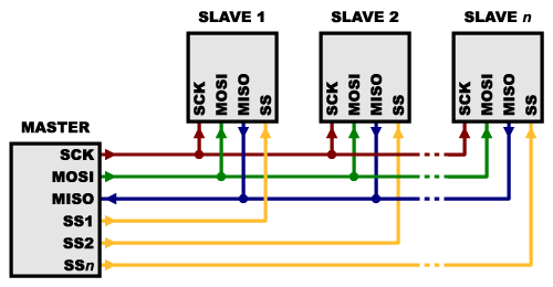
Multiple Slaves:
- By giving each slave a separate SS lines. By enabling and disabling that SS line we can control that particular slave.
Tips:
- Because of the high speed signals, SPI should only be used to send data over short distances.
- For long distance communications decrease the clock speed and consider using SPI drivers etc.
No comments:
Post a Comment